top of page

THE TELEGRAPH PAGE

Having been a railroad telegrapher in my past life, I have a small collection of telegraph instruments which I will show on this page.

MY ORIGINAL VIBROPLEX BUG, 1939

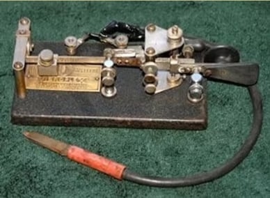
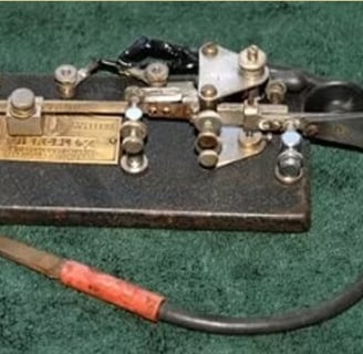
This is my original Vibroplex bug from 1939, SN 111779.

I have owned this bug since the early 60's so I suspect that I am its second owner. I was working for the GTW RR in Michigan and purchased this from an old time railroad telegrapher.


That funny looking plug on the end of the cord was inserted into the slide switch of a straight key so that the semi-automatic bug could be used. There is a shorting bar on this bug on the far side that you can't see.


On land-line telegraph you must always close the circuit with the shorting bar, otherwise no one can send anything if you leave it open.

VIBROPLEX BUG WITH CASE FROM 1944

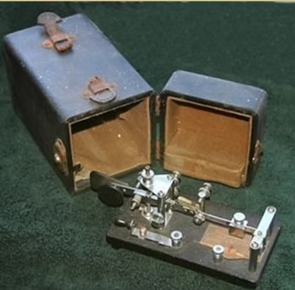
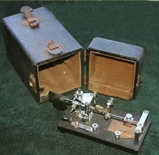
This is a Vibroplex bug with it's carrying case. This one has SN 127436 and is from 1944.


The leather handle on the case is broken which shows that this was used a lot in its day.


On this one you can see the shorting bar slide switch in the foreground. As mentioned above, another person could not send a signal unless you remembered to close your shorting switch.

1975 VIBROPLEX BUG

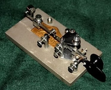
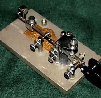
This bug has serial number 378007 and is from 1975.


Notice that this one has a grey finish, instead of the more common black wrinkle finish. I am missing a couple of parts for this bug but most parts are still available from Vibroplex.

VIBROPLEX BUG FROM 1976

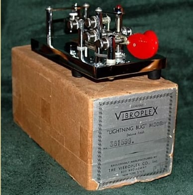
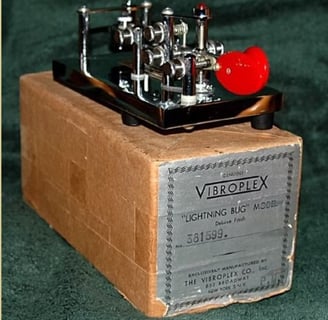
This is a Vibroplex Lightning Bug from 1976. The serial number is 381599.


This bug is new and in its original box. This model has a chrome base and it drives me nuts keeping the finger prints off of it when I handle it.....so I try not to handle it!


I keep this one wrapped in plastic in its box and take it out for show and tell when friends are over.

SPARK PROOF NAVY KEY

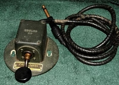
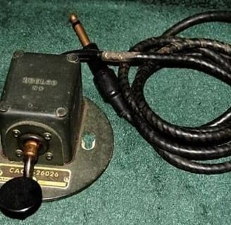
This spark proof key is made by Brelco, NY and is model CAQZ-26026.


There is also some other numbers on the face plate. One that is a permanant part of the plate is NXsr-60008 and the serial number is stamped on the plate as 4464.


These keys were used in environments where "sparks" could ignite fumes from flamable, or combustable, material. The key contacts are totally enclosed in that box and sealed from the elements. Not only does this prevent sparks, but it also provides a salt-free atmosphere aboard ships to prevent corrosion of the contacts.

STRAIGHT KEY WITH MARBLE BASE

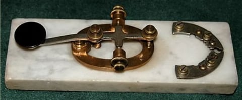
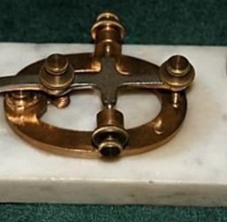
Here is an unusual straight key with a marble base.


I suspect this was a homemade project but the terminal strips on the right are something I have never seen before.


The base is very heavy and it has felt pads so it sets above the interconnect wires. However, one of the wires sits in a grove someone cut into the bottom.


Note that there is no shorting bar on this key so it was intended for RF work.

MANHATTAN LAND LINE KEY

This is a Manhattan Land Line telegraph key. There is no model number evident.


Unlike the key above, this one does have the shorting bar so it was intended for land line use.


The base is wood and looks as if it has been turned on a lathe, and a very nice job indeed! Although the base has been hollowed out, it still makes for a very stable platform.

MY FIRST TELEGRAPH SOUNDER

This is my first telegraph sounder. It is a WUTCO model 1B, with two 200 ohm coils.

Sounders usually have only 2 terminals but this one has 2 for each coil. I understand this is so that the user could select either 200 ohm or 400 ohm operation. Each coil is 200 ohms. I have had this one since working on the GTW RR in the early 60's.

Many times you would see these mounted in a triangular echo box with one side open to give the sound a little amplification. Then it was common to place a Prince Albert tobacco tin between the sounder and the echo box to give it a unique sound.


Remember, in a place such as a large Western Union Telegraph Office in a major city they would have a room full of operators with all the clickity-clack sounds fillng the room. Therefore, it was necessary for some operators to modify the sound (such as using the tobacco can) so they could "focus" on their message and not be distracted by all the other noises in the room. I guess no one thought of hooking the sounders up to headphones so they would not be distracted by the others.


You may have seen the echo boxes on something like a telescopic arm which was used so the operator could get HIS (or HERS) sounder right up close to their ears. In this way also they were able to focus only on their signal.

I have since built my own sounder echo box complete with a Prince Albert tobacco can with lid. It is amazing how you can modify the sound by opening and closing the lid by various amounts.


Imagine a Western Union office in a big city where there might be a dozen telegraph operators in the same room. Using something like this they could adjust their sound to make it different from all the other chattering sounders in the room.


Also, pointing the open side of this box focuses the sound on the operator, further reducing the interference from those around them.


I use this setup when I am displaying telegraph items for folks to enjoy. The first time I used this on display was at a Civil War re-enactment and I had a straight key connected to it so the kids could see what signals sounded like when the Union Officers sent messages to President Lincoln!

CENCO, 4 ohm Sounder

This is a CENCO, 4 ohm sounder. I don't have a date for this.

Now you can see what the USUAL sounder looks like with just two terminals.


The armature was the means of READING the land line Morse Code. When the coils were energized the armature would be pulled down and a loud click was heard. When the coil was de-energized the armatur would go back to the top, being driven by the spring on the left, and a clack sound was heard.


Notice that the pull down sound was different from the spring up sound. I refer to the sound difference as click and clack, but you could state it as clack and click. The important thing is that the sound was different so the operator knew the start of a dash and dot compared to the end of a dash or dot.

BUNNEL & CO SOUNDER

This Bunnel & Co. sounder has no model numbers or coil resistance written on it.


Again we have a two terminal device, but on this one there is some interesting gold painted leaves on the metal base. It gives the sounder a little more of an artistic presence, not just a electro-mechanical device that makes noise.

HOME BREW TELEGRAPH SOUNDER

Believe it or not, this is a home brew telegraph sounder. This was given to me by a friend who bought it on eBay because he wanted it to go to a good home.


This is a cute, but primitive home made sounder. The coils almost look like spools of thread. I have not hooked this up to a battery yet to see if it actually works, but I can imagine that the sound made by the armature would be totally different from the professional models above.

WESTERN UNION MAINLINE SOUNDER

This is a W. U. Tel. Co. main line sounder model 15B with 120 ohm coils.


This particular model is different from most in that the armature plate is set at an angle and there is a lever operated cam on the right side of the picture to adjust the gap between the solenoid and the armature.

The lever actually moves the solenoid left and right, thereby opening or closing the distance between the top of the solenoid and the armature plate.


This one still needs a good clean up. There is a square stamp on the bottom that says N.Y.R.S., 1409, inspected.

WESTERN ELECTRIC SOUNDER

WITH SILENCER

This is an unusual Western Electric Sounder for two reasons.


First it has that strange cast iron horseshoe on the left which will give this sounder a distinct sound.


Second is that it has a "silencer" switch on the upper right which could be rotated out over the sounder bar to keep it from clicking.


There are a lot of variations to the horseshoe, but I have never seen the silencer before so I just had to have this one.

MULTI-LINE RELAY

This relay has one line in and two lines out. This unit is on a very heavy base and is in excellent condition.

I could not find a name or model number so if you can identify this then please contact me at wa6dij at arrl dot net. ( I just learned that this is a Western Electric Model 26A)


Relays were used to transfer the signal from one line to another. For example, a local line may have only a 30V battery while the main line may run off of a 90 volt battery. By using a relay you can isolate the two electrical potentials and send the signal out over the other line.


In this example there is a double set of breaker points and a double set of terminals going out. Two terminals on the right end of the unit are for the input line and a pair of terminals on the left side of the unit are for each of two different lines.

MESCO PONY RELAY

This is a MESCO Pony Relay.

There is some information on this relay in the Coyne Electric & Radio School books, Volume 1, Page 81 if you have that reference.


On relays you expect four terminals like this one has. That is because they were used to "relay" signals from a local line onto a main line, or from one main line section to the next.


A signal would come in on one set of terminals and that would actuate the coils which would make electrical contact to the other set of teminals. The two sets of wires (terminals) were isolated from each other so you could have different voltages powering the two circuits. There were different kinds of relays made. Some were called "mainline" relays and others were called "local" relays. There were probably many other variations.

RAILROAD RULE BOOK

This is a Rule Book from the Chicago, Milwaukee, St. Paul and Pacific Railroad Company dated 1959.

There are all kind of rules in this book, but all having to do with the "rolling stock" of the railroad. The rules include items such as the whistle signals used by the engineer for moving the train forward, backward, stop, and grade crossings. The whistle signals are very similar to Morse Code in that they use a combination of long and short whistle blasts. Like CW operators, train engineers have their own "signature" when blowing whistle signals. Just listen to a train in your area as it approaches a road (grade) crossing. The signal is two longs, a short and one long. Some engineers make the last "long" about 3 - 4 times as long as the beginning longs. Be sure to listen!

There are also rules for lantern signals that are used at night to govern the movement of trains in a freight yard. The brakeman on the ground will give the lantern signal to back up when coupling to a new car and the engineer may reply with a whistle signal, if required by the rules, or he may just respond by backing up as directed by the brakeman. During daylight hours the brakemen use hand signals, but they are identical to the lantern signals.


I worked as a RR Telegrapher and I was required to "inspect" trains as they passed. So a common signal for me was to pinch my nose with my left hand and swing my right hand horizontally back and forth. This signal meant the train had a "hot box" and must stop for inspection. The axle journals on trains are packed with some cloth-like material and soaked with oil. When the bearing gets hot this oil soaked material may catch on fire. It is pretty stinky so the hand signal is pretty descriptive of the problem.


There are rules governing the writing and issuing of train orders and rules governing the electric light signals and semaphore signals found along the rail lines.


Some good info can be found here: http://www.du.edu/~jcalvert/railway/railhom.htm


When I worked on the RR, everyone who worked out on the line (non office workers) had to "Write the Book". This was a required test everyone must take to see how well you understand the rules spelled out in the rule book. Every railroad has its own rule book, but they are all very similar.

Next page, click HERE

Return to top of page, click HERE

bottom of page